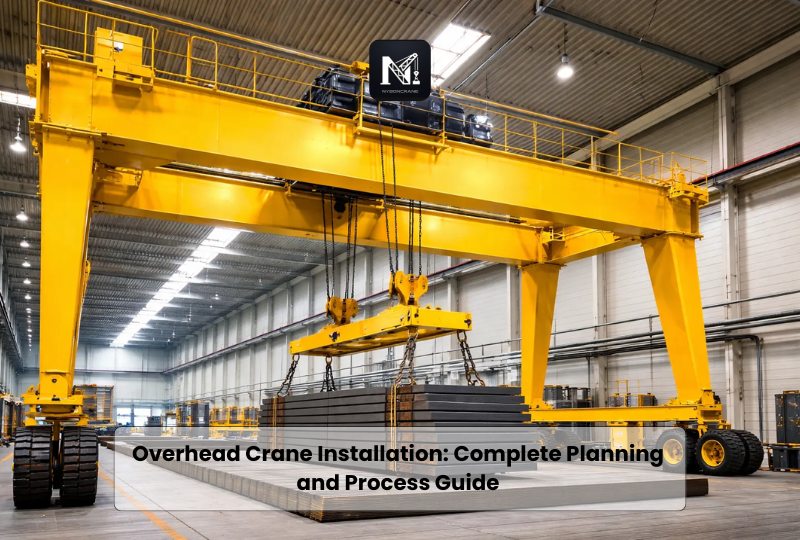
Overhead crane installation is more than placing a crane inside a building. It is a coordinated engineering project involving structural steel, mechanical components, electrical systems, and safety controls.
A successful installation begins with accurate measurements and proper crane selection. It ends with inspection, operational testing, commissioning and documentation.
Even a well-designed crane can develop problems when installed incorrectly. Poor runway alignment may cause skewing, wheel wear and vibration. Incorrect electrical connections can affect motors, brakes and control systems. Structural errors can create much more serious risks.
This guide explains the complete overhead crane installation process. It covers planning, crane components, site requirements, installation steps, safety standards, testing, cost and maintenance.
What Is Overhead Crane Installation?
Overhead crane installation is the process of assembling, positioning, connecting, and commissioning an overhead lifting system.
The crane may be supported by the existing building structure. It may also use an independent steel runway supported by columns and foundations.
The installation normally includes the crane bridge, end trucks, runway rails, trolley, hoist, electrical supply and control system. Safety devices are also installed and tested before operation.
The process requires structural verification, mechanical assembly, electrical integration and functional testing. It should be completed by qualified engineers, riggers, electricians and crane technicians.
Is an Overhead Crane the Same as a Bridge Crane?
The terms overhead crane and bridge crane are often used interchangeably.
The bridge is the horizontal structure that moves along elevated runways. A trolley travels across the bridge, while the hoist raises and lowers the load.
An electric overhead traveling crane is also called an EOT crane. These systems are commonly used in workshops, warehouses, steel mills, manufacturing plants and maintenance facilities.
Main Components Installed in an Overhead Crane System
Understanding the main components helps buyers define the project scope.
1. Crane Bridge
The bridge spans the working area. It travels along runway rails positioned on opposite sides of the building.
A single girder crane has one main bridge girder. A double girder crane uses two parallel girders.
2. End Trucks
End trucks are located at both ends of the bridge. They contain wheels, bearings, motors and drive components.
The wheels allow the bridge to travel along the runway.
3. Runway Beams and Rails
Runway beams transfer crane loads into the building columns or an independent support structure.
Crane rails are attached to the runway beams. They must be straight, parallel, level and properly spaced. CMAA Specifications 70 and 74 provide widely used guidance for crane design and runway alignment.
4. Trolley
The trolley moves horizontally across the bridge. It carries the hoisting mechanism and positions the hook across the crane span.
5. Hoist
The hoist raises and lowers the load. It may use wire rope or chain, depending on capacity, lifting height, speed and duty requirements.
6. Electrification System
The electrification system provides power to the crane and trolley. Common options include conductor bars, festoon cables and cable reel systems.
7. Crane Controls
Crane controls may include a pendant station, wireless remote control, operator cabin or automated control system.
Variable frequency drives may be added for smoother acceleration and more precise positioning.
8. Safety Devices
Important safety components include brakes, travel limit switches, hoist limit switches, overload protection, emergency stops, bumpers, warning alarms and runway end stops.
Types of Overhead Cranes and Their Installation Requirements
The installation method depends on the crane configuration.
Single Girder Overhead Crane Installation
A single girder crane uses one bridge beam. The hoist normally travels beneath the girder.
This configuration is commonly used for light and medium material handling. It usually places less weight on the building structure than a comparable double girder system.
Single girder cranes may also provide a simpler installation when capacity, span and duty requirements are moderate.
Double Girder Overhead Crane Installation
A double girder crane uses two bridge beams. The trolley often travels on rails mounted above the girders.
This design is suitable for higher capacities, longer spans, demanding duty cycles and greater lifting heights. It may require larger runway beams, stronger columns and more installation equipment.
Top Running Crane Installation
A top running crane travels on rails positioned above the runway beams.
This arrangement is frequently used for higher capacities and wider spans. The runway system must support vertical wheel loads, lateral forces and crane movement.
ASME B30.2 covers the installation, operation, inspection and maintenance of certain top running overhead and gantry cranes.
Under Running Crane Installation
An under running crane, also called an underhung crane, travels on the lower flange of a runway beam.
It can be supported by roof framing or a separate steel structure. Building capacity and connection points must be evaluated before installation.
ASME B30.17 contains provisions for overhead cranes and monorail systems with an underhung trolley, bridge or both.
Freestanding Overhead Crane Installation
A freestanding crane uses independent columns rather than relying entirely on the building.
This can be useful when the existing structure cannot support crane loads. It may also suit facilities where the crane needs to operate in a specific production area.
Depending on the design, the system may require concrete foundations, anchor bolts, bracing and additional floor preparation.
Information Required Before Installing an Overhead Crane
Accurate project information reduces engineering changes and installation delays.
The following details should be confirmed before manufacturing begins.
Rated Lifting Capacity
The rated capacity is the maximum load the crane is designed to lift.
The selected capacity should account for the actual load, lifting attachment and any below the hook equipment. Future production requirements should also be considered.
Crane Span
The span is the horizontal distance between the crane runway rails.
It must be measured accurately at several locations. Existing buildings are not always perfectly square or parallel.
Lifting Height
Lifting height is the vertical distance the hook must travel.
Available headroom, roof height, equipment height and floor level affect the final lifting height.
Runway Length
The runway length determines how far the bridge can travel through the facility.
It also affects rail quantity, electrification length, support steel and installation time.
Duty Class
Duty class reflects how frequently the crane operates and how heavily it is used.
A crane making occasional maintenance lifts has different requirements from a crane operating continuously in a steel plant.
Motor sizing, brakes, wheels, bearings, hoist selection and structural design can all be affected by duty class.
Operating Environment
The supplier should know whether the crane will operate around dust, moisture, chemicals, heat, corrosive materials or explosive atmospheres.
Special environments may require protective coatings, sealed electrical equipment, heat resistant components or explosion protected systems.
Power Supply
Voltage, frequency, phase and available electrical capacity must match the crane design.
The location of the building power connection should also be confirmed.
Control Method
Buyers should specify whether the crane will use pendant control, wireless remote control, cabin control or automation.
Local Standards
Crane requirements differ between countries and regions.
The manufacturer, engineering team and installer should identify the applicable crane, structural, electrical, building and occupational safety standards before approving the design.
Pre Installation Site Assessment
A site assessment should be completed before the crane is manufactured or shipped.
The assessment normally covers the building, runway, floor, access route, power supply and installation area.
Structural Evaluation
A qualified structural engineer should verify that the supporting structure can handle the crane.
The evaluation may consider:
- Crane dead weight
- Maximum lifted load
- Hoist and trolley weight
- Vertical wheel loads
- Lateral forces
- Longitudinal forces
- Impact and dynamic loading
- Runway beam deflection
- Column and foundation capacity
- Existing structural condition
OSHA requires crane modifications and supporting structures to be checked for the new rated load when a crane is modified or rerated.
Installation Access
The installation team must be able to bring bridge girders, end trucks, hoists and runway components into the building.
Door size, loading areas, internal aisles and turning space should be checked.
The site may also need access for a mobile crane, boom lift, scissor lift, forklift or other erection equipment.
Installation Work Area
The area should be cleared before the crew arrives.
Production equipment, stored materials and vehicles should be removed from the lifting zone. Barricades should prevent unauthorized access during installation.
Electrical Preparation
The customer and installer should confirm who will provide:
- Main electrical supply
- Disconnect switch
- Conduit and cable routing
- Grounding connection
- Final power connection
- Electrical inspection
- Temporary construction power
Responsibilities should be written into the contract before installation starts.
Complete Overhead Crane Installation Process
The exact procedure varies by crane design and site conditions. Most projects follow the stages below.
Step 1: Finalize Engineering and Drawings
The manufacturer prepares general arrangement drawings, runway details and electrical specifications.
These drawings normally show capacity, span, lifting height, hook approach, wheel loads, clearances and connection points.
The customer, building engineer and installer should review the drawings before production.
Changing the span, height or runway after manufacturing can create delays and additional costs.
Step 2: Prepare the Supporting Structure
For a building supported crane, runway beams and support brackets are installed or inspected.
For a freestanding crane, the work may include foundations, anchor bolts, columns, bracing and runway beams.
Concrete must reach the required strength before crane loads are applied.
Step 3: Install and Align Runway Rails
Rails are positioned on the runway beams and secured using approved clips, fasteners or welding methods.
The crew checks:
- Rail span
- Rail straightness
- Rail elevation
- Parallelism
- Rail joints
- Fastener condition
- Runway end stops
The project drawings and manufacturer tolerances should control the final alignment.
Step 4: Receive and Inspect Crane Components
Crane components are checked when they arrive at the facility.
The crew looks for shipping damage, missing hardware, damaged paint, loose connections and incorrect components.
Girders, end trucks, hoists and electrical equipment should be stored in a clean and protected area until erection begins.
Step 5: Assemble the Bridge
The bridge girder and end trucks may be assembled at floor level.
Bolted connections are tightened according to the specified torque. Drive shafts, wheel assemblies, platforms and other components are installed as required.
For a double girder crane, both girders must be positioned and connected accurately.
Step 6: Lift the Bridge Onto the Runway
A mobile crane, lifting system or other approved equipment raises the assembled bridge.
A documented lifting plan should define the load weight, lifting points, rigging equipment, crane position and communication method.
Only necessary personnel should remain within the controlled lifting area.
The bridge is then placed carefully onto the runway rails.
Step 7: Install the Trolley and Hoist
The trolley and hoist may be installed before or after bridge erection. The method depends on component weight, access and crane design.
The crew checks wheel engagement, trolley alignment, rope reeving, hook block assembly and mechanical clearances.
Step 8: Install the Electrification System
The runway power system is installed along the crane travel path.
The system may use conductor bars, festoon cables or another approved method.
Trolley electrification is then installed across the bridge.
Step 9: Connect Motors and Controls
Electricians connect the bridge motors, trolley motors, hoist motor, brakes, control panel and safety devices.
The installation should verify correct voltage, phase rotation, grounding, cable protection and motor direction.
Pendant stations, wireless receivers and cabin controls are also connected.
Step 10: Install Safety Components
Safety devices are fitted and adjusted according to the manufacturer’s instructions.
These may include:
- Upper and lower hoist limits
- Bridge travel limits
- Trolley travel limits
- Emergency stop controls
- Overload protection
- Audible and visual warnings
- Bridge bumpers
- Runway end stops
- Anti collision devices
- Rail sweeps
Step 11: Complete Mechanical Alignment
The installer checks bridge squareness, wheel alignment, trolley movement and rail contact.
Bolts, couplings, gears, brakes and drive assemblies are inspected.
The crane should travel smoothly without unusual noise, binding or excessive wheel flange contact.
Step 12: Perform Operational Testing
Before initial use, the crane is operated without a production load.
The test should verify:
- Hoisting and lowering
- Trolley travel
- Bridge travel
- Motor direction
- Brake operation
- Control response
- Limit switch operation
- Emergency stop function
- Warning devices
- Smooth acceleration and deceleration
OSHA 1910.179 requires an initial inspection and operational testing of new and altered cranes before initial use when the standard applies.
Step 13: Conduct the Rated Load Test
Many crane projects include a rated load test during commissioning.
The test confirms the performance of the bridge, trolley, hoist, brakes, controls and supporting structure under load.
Where OSHA 1910.179 applies, the test load must not exceed 125 percent of rated capacity unless the manufacturer recommends otherwise. Test reports must be kept where appointed personnel can access them.
The exact test load and procedure should follow the applicable standard, manufacturer instructions and local regulations.
Step 14: Complete Final Inspection and Handover
After testing, the installer completes a final inspection.
The customer should receive:
- Approved drawings
- Operating manuals
- Electrical diagrams
- Inspection report
- Test documentation
- Component certificates
- Warranty information
- Recommended maintenance schedule
- Spare parts information
- Operator training records
Project documentation supports future inspections, repairs, modifications and regulatory reviews.
Maintenance After Overhead Crane Installation
Installation is the beginning of the crane’s working life.
A preventive maintenance program should be created using the manufacturer’s recommendations and applicable regulations. OSHA 1910.179 requires such a program for cranes covered by the standard.
Maintenance planning should cover:
- Brakes
- Hooks
- Wire ropes or chains
- Wheels and rails
- Bearings and gears
- Motors
- Electrical contactors
- Limit switches
- Pendant and remote controls
- Lubrication points
- Structural connections
- Runway alignment
Inspection frequency should reflect operating hours, service severity and environmental conditions.
New unusual noises, wheel flange contact, vibration or inconsistent travel should be investigated promptly.
Overhead Crane Installation Checklist
Before installation begins, confirm the following:
- Crane capacity has been approved.
- Span and lifting height have been verified.
- Duty class matches actual usage.
- Building structure has been assessed.
- Runway drawings have been approved.
- Rail alignment requirements are available.
- Foundations have reached the required strength.
- Required permits have been obtained.
- Power supply information is correct.
- Main disconnect and connection point are ready.
- Delivery access has been checked.
- The installation area has been cleared.
- Mobile crane and lift access is available.
- Installation responsibilities are documented.
- Test weights or another test method are available.
- Operators are scheduled for training.
- Inspection and testing requirements are confirmed.
- Final documentation requirements are included in the contract.